Week 8, Assignment 8
Embedded Programming
Video - Week Eight, Lecture Eight
Goal
This week assignment was all about controllers, processors, etc. which will be programmed to do things like a mini computer. The most common microcontroller used in FabLab is the ATTiny Series. They are all AVR microcontroller's, and I will be programming the board I made in Week 6 - Electronics Design.
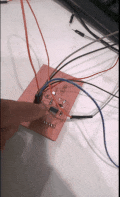
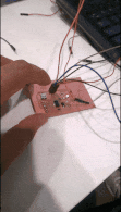
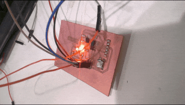
I made echo-hello board with Attiny44 microcontroller which can be programmed using the FabISP, which I made in Week 4 - Electronics Production. The board I made have a LED and a press button switch attached. So I can program the board to do some basic tasks like blinking the LED.
Datasheet:
A Datasheet is a instruction manual for electronic components. It thoroughly explain exactly what a component does and how to use it. Unfortunately these documents are tightly packed with the information and hence can often be difficult and super confusing to read, especially for beginners. Datasheets are still the best place to find the details you need to design a circuit or get one working.
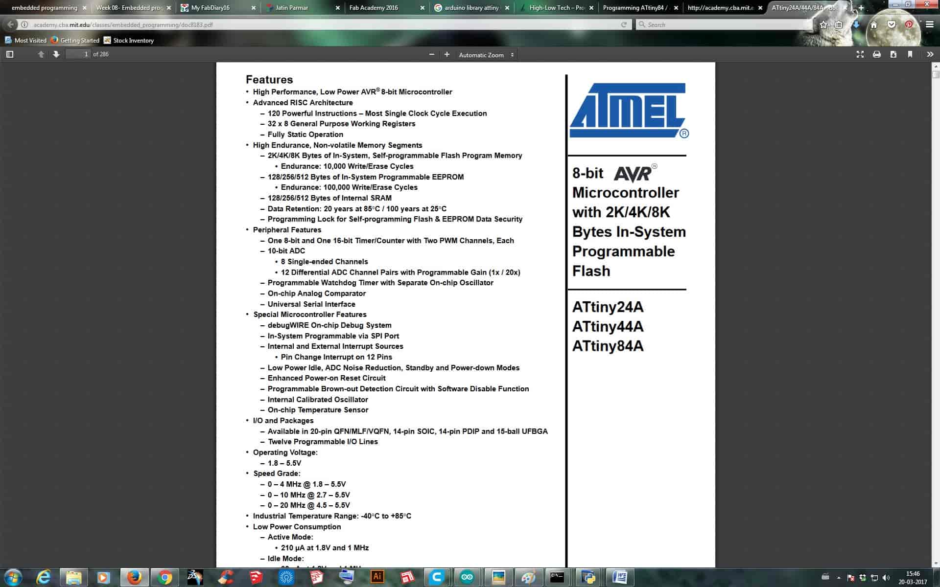
The above image shows the part number for which the datasheet is applicable for which is ATtiny series microcontroller devices. This data sheet which I was referring is applicable for ATtiny24A/ ATtiny44A/ ATtiny84A. The part number tells us that the given microcontroller is specifically a Atmel 8-bit AVR Microcontroller with 2/4/8K Bytes In-System Programmable Flash.
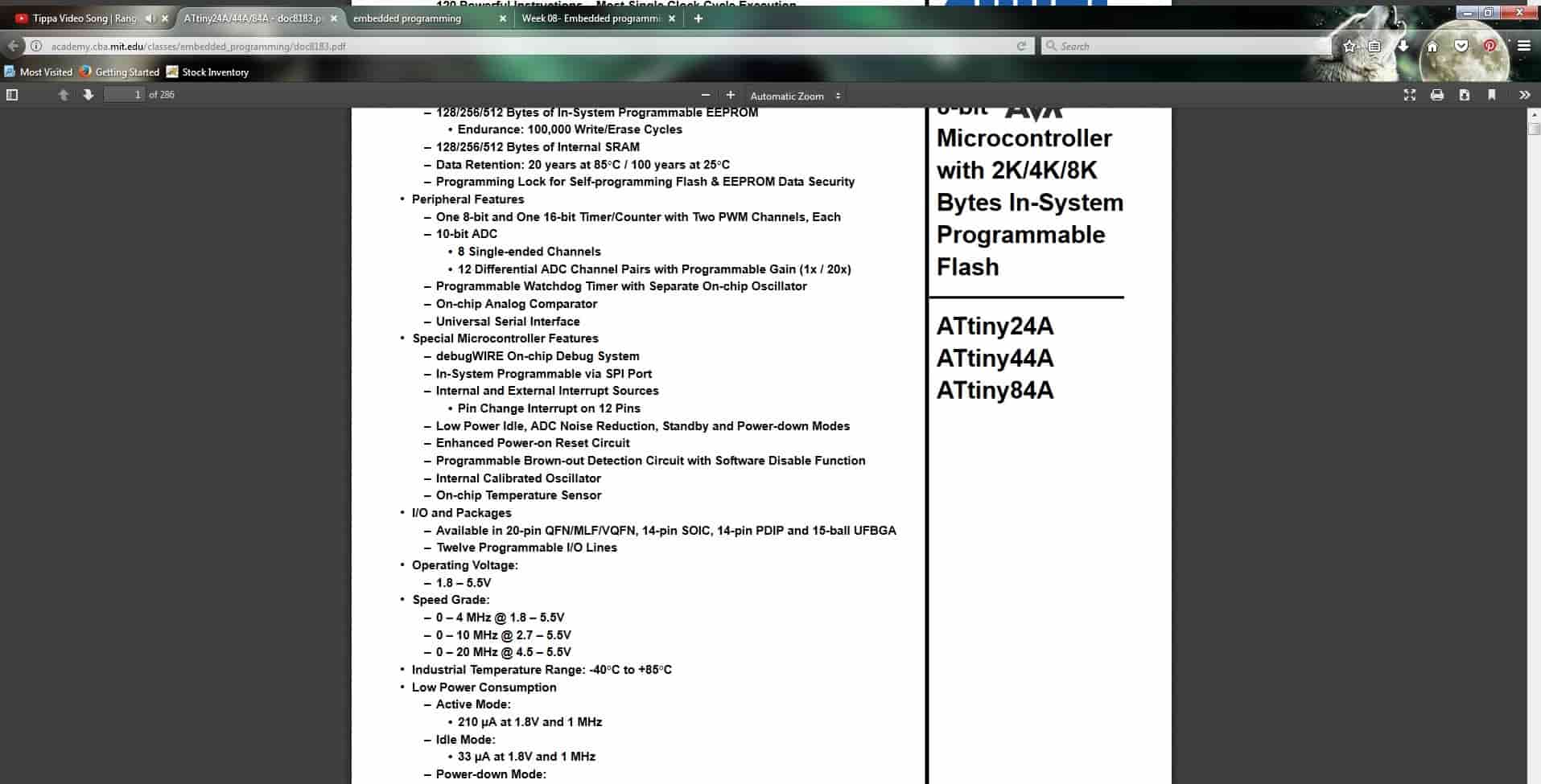
The above Image shows the Power conditions of the ATtiny microcontroller. It tells us that the ATtiny IC is designed to work between the voltage range of 1.8V to 5.5V. So exceeding this values will fry the device. Then it tells about the clock speed that we can use and which we can't use while voltage variations. The other special feature tells about the different power saving options.
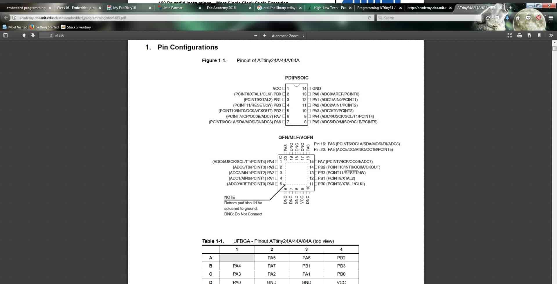
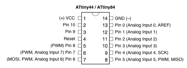
The above Image now shows all the pin configuration of ATtiny 44A IC. This helps a lot to know how and where to connect any PIN with a specific number while coding.
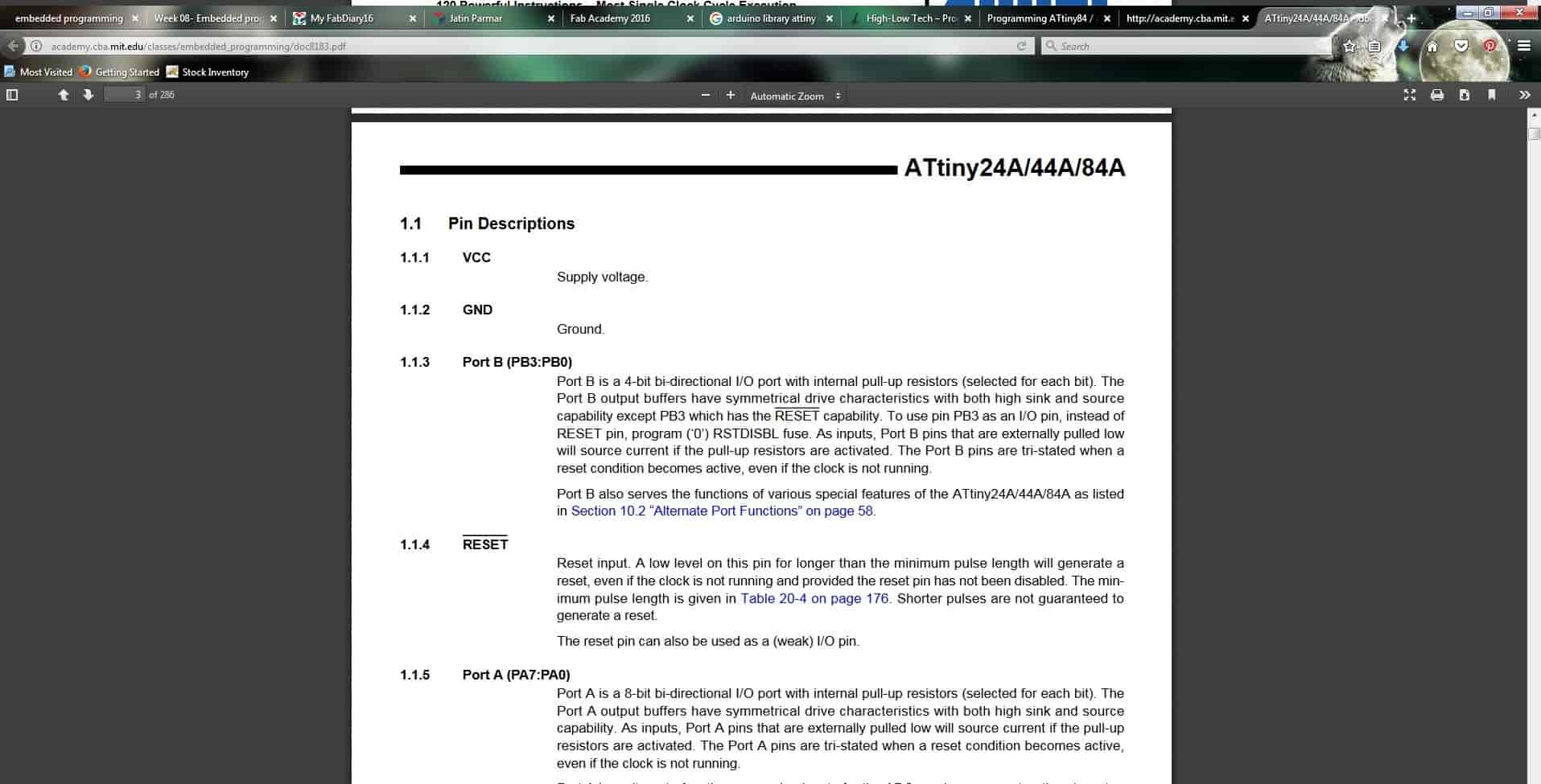
Now the above image describes the PIN of ATtiny 44A in detail. It shows that ATtiny 44A and two different Ports with different meaning and a VCC(supply voltage) pin, a GND (ground) pin, and a RESET pin. Port A & B are almost the same, there have 4-bit bi-directional I/O port with internal pull-up resistors. The output output buffers have symmetrical drive characteristics with both high sink and source capability. Except in PORT B, which has the RESET capability in PB3 Pin.
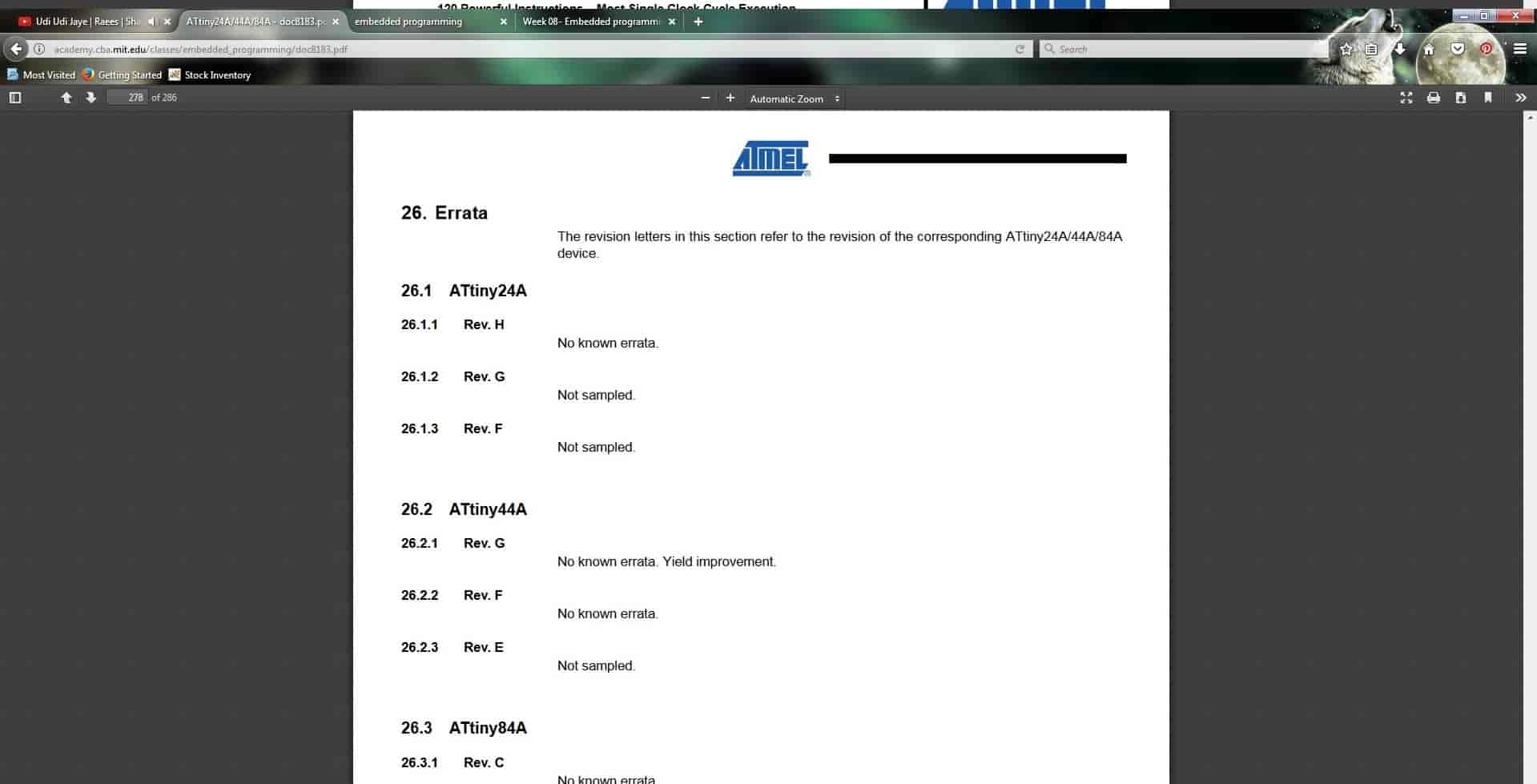
Errata section lets us know about all the updates and corrections to a parts specification usually found after the production of the part. If sometimes we are able to understand the error which is occurring in the circuit without solution in datasheet also then this is the place where we can find it, it tells us where and what's wrong in datasheet also and suggests the method to work with.
Programming:
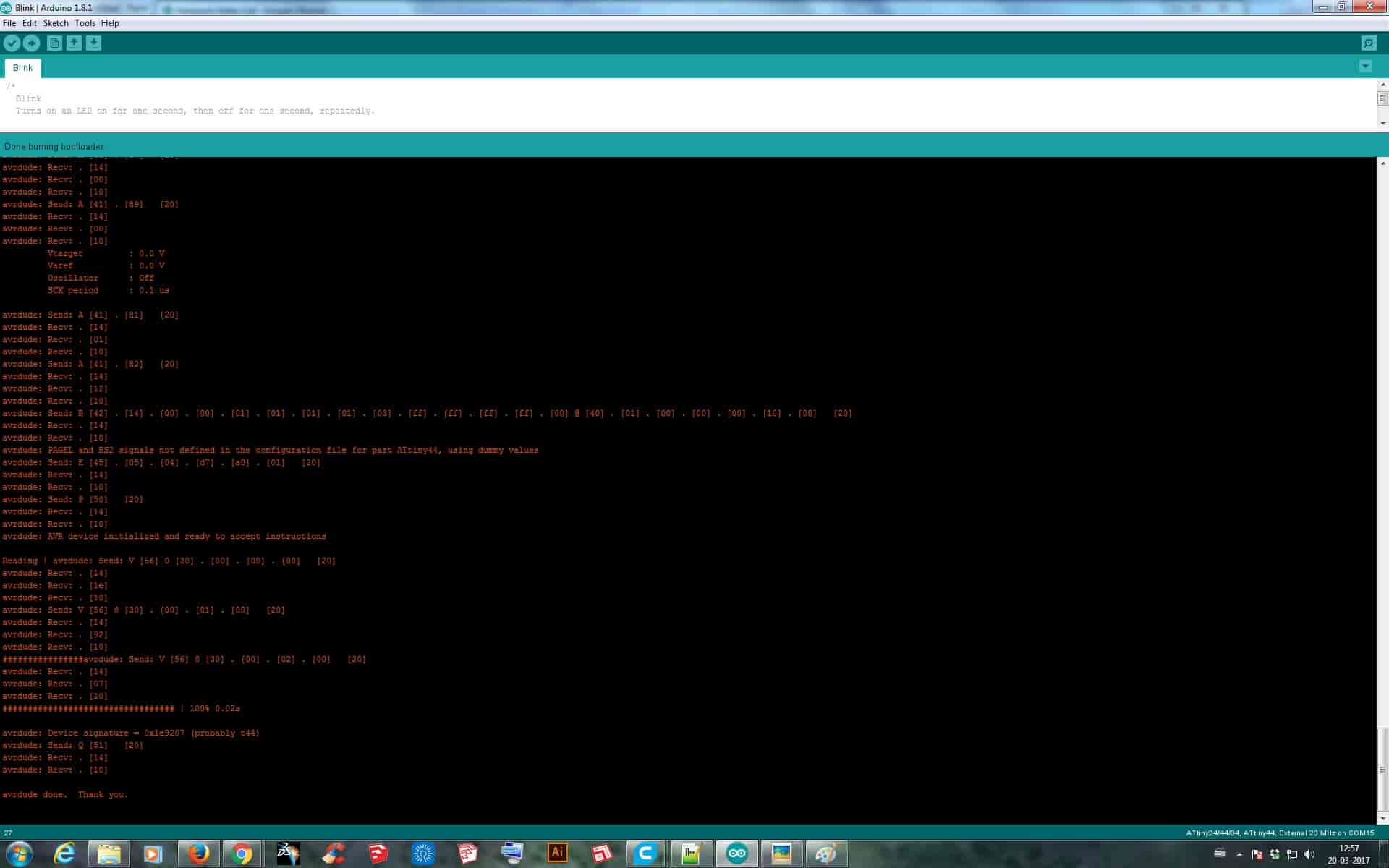
I used the latest version of Arduino 1.8.1 and as it was not having the ATtiny board added prior so I added the Board following the steps in this Link and added Board, which was then showed in the Tools drop-down menu. Then I figured to which Pin my LED was connected, where the Data Sheet helped a lot. Presently but the following image given below helped a lot to get the PIN number for coding.
After doing the required setting I then just tried to Burn Bootloader and as it worked fine I knew now that I can Proceed with coding.
So with the help of both Pin out image and data sheet I wrote the code for blinking the LED continuously.
int led=7;//declaration of pin
void setup() {
pinMode(led,OUTPUT);//Initialization of output pin
}
void loop() {
digitalWrite(led,HIGH);//state of pin to go high
delay(100);
digitalWrite(led,LOW);//state of pin to go high
delay(100);
}
After the above code, I then tried to write the code to turn LED ON and OFF with the help of switch connected to PIN 2 which was a Analog PIN so wrote code accordingly for the board.
int led=7;
int button=A2;
void setup() {
pinMode(led,OUTPUT);
}
void loop() {
if(analogRead(button)>200)
{
digitalWrite(led,LOW);
delay(100);
}
else
digitalWrite(led,HIGH);
delay(200);
}
Then after making code for button ON and OFF of LED, I then wrote a command for making the LED ON when I once pressed the button and then OFF when I again press the button.
int led=7;
int button=A2;
int counter=0;
void setup() {
pinMode(led,OUTPUT);
digitalWrite(led,LOW);
}
void loop() {
if(analogRead(button)<200)
{
if(counter==0)
{
digitalWrite(led,HIGH);
delay(10);
counter=1;
}
else
{
digitalWrite(led,LOW);
delay(10);
counter=0;
}
delay(500);
}
else
delay(10);
}
AVR-C:
After trying the codes in Arduino IDE, I then decided to try AVR-C. In this way of programming data sheet is the most useful thing as I need to get data like number of ports, pin numbers, internal architectures, information on registers, etc. So first I wrote a code for blinking the LED, which came after a long tutorial on Youtube about Programming.
#include
#include
int main(void)
{
DDRB = 0b00000100;
while(1)
{
PORTB = 0b00000100;
_delay_ms(1000);
PORTB = 0b00000000;
_delay_ms(1000);
}
}
Then as after the above program I made a program which would use button for switching the LED ON and OFF according to the push.
#include
#include
int main(void)
{
DDRB = 0b0100;
DDRA = 0b10000000;
PORTB = 0b0000;
PORTA = 0b10000100;
while(1)
{
if(!(PINA & 0b00000100))
{
PORTB |= 0b0100;
PORTA &= 0b01111111;
}
else
{
PORTB &= 0b1011;
PORTA |= 0b10000100;
}
}
}
Blinking:
Button